EasyAR Dense Spatial Map
Overview
DenseSpatialMap generates 3D mesh of the environment by performing 3D reconstruction using RGB input. The mesh created by DenseSpatialMap makes virtual objects interacts seamlessly with the physical world. You can design AR application with object occlusion and physcial collision.
EasyAR Dense Spatial Map needs RGB images as well as their corresonding poses as input, which one can get from modern motion tracking systems such as EasyAR MotionTrackerCameraDevice or ARKit/ARCore. DenseSpatialMap itself does not support relocalization, for which you can use EasyAR SparseSpatialMap.
The coordinate system of DenseSpatialMap is right-handed: when the user holds device facing forward, the x-axis points to the user’s right, the y-axis points to the top, and the z-axis points to the user. The definition of this coordinate system is consistent with the widely used APIs such as OpenGL, ARKit and ARCore. Unity uses left-handed coordinate system, whose z-axis is opposite to the right-handed coordinate system. Therefore, coordinate conversion is required when used in Unity. You can find the transformation method in Our Unity demo.
Introduction of mesh map
In this section we give detailed introduction of the mesh map we use through DenseSpatialMap. We assume you have prior knowledge about 3D graphics. If you are unfamilar with mesh, we suggest you read the following materials first.
https://en.wikipedia.org/wiki/Triangle_mesh
For Unity users please refer to:
https://docs.unity3d.com/ScriptReference/Mesh.html
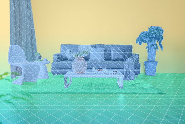
The figure below is a schematic diagram of a grid map.

Fig 1. mesh map
We view mesh as an approximation of the surface of 3D object and enviornment. Physical objects has nearly infinite resolution. To store and use the surface information in computer, we need to reduce the resolution by approximating the surface with many interconnected triangular planes, each of which is composed of three vertices on the surface. The mesh map is made up of vertices and faces. Each vertex denotes one 3D point and each face contains three indices, which describe the three vertices that form this plane.
In the APIs of DenseSpatialMap , a vertex is composed of 6 numeral : (x, y, z, nx, ny, nz), in which (x, y, z) is the world coordinates of the vertex and (nx, ny, nz) is its normal vector. The normal vector describes the direction the point is facing, which is used for light rendering and collision physics. A triangular face is made of 3 numeral: (i1, i2, i3), each of which represents an vertex of the triangle with its index in the list of vertices. The three indices (i1, i2, i3) are arranged counterclockwise.
Mesh Buffer
For the convenience of transformation and make it more user-friendly, we use 3 Buffers – Vertex Buffer, Normal Buffer and Index Buffer, to store positions, normal vectors and indices of triangle mesh respectively.
Data in Vertex Buffer and Normal Buffer are stored in 32-bit floating-point numbers, each of which takes up 4 bytes. Every three consecutive numbers in Vertex Buffer form a vertex’s 3D coordinates, so each element takes 4*3 = 12 bytes. Analogously, every three consecutive numbers in Normal Buffer form a vertex’s normal vector, so each element takes 4*3 = 12 bytes. The order of Vertex Buffer and Normal Buffer are the same. For example, the 37~48th bytes of Vertex Buffer describe the position of 4th vertex and the 37~48th bytes of Normal Buffer describe its normal vector.
Data in Index Buffer are stored in 32-bit integer numbers, each of which takes 4 bytes. A triangle mesh is composed of 3 vertex, but we use index to represent vertex, such that we can re-use and share vertex in different triangle mesh. The index here refers to the order a vertex stored in the Vertex Buffer. For example, if a triangle mesh’s three indices are (1, 4, 9), that means the triangle mesh is composed of the 1st, 4th and 9th vertex stored in Vertex Buffer. Each triangle mesh also takes 4*3 = 12 bytes.
Note: The Vertex Buffer, Normal Buffer and Index Buffer here are similar to the definitions in OpenGL, Unity and other 3D engines.
Block Info
Since the reconstruction process is incremental, the map size will gradually increases. If all the map data is updated every time, the data transmission and computation requirements will be intractable soon. we chose to split the map and update the part of the map only when needed.

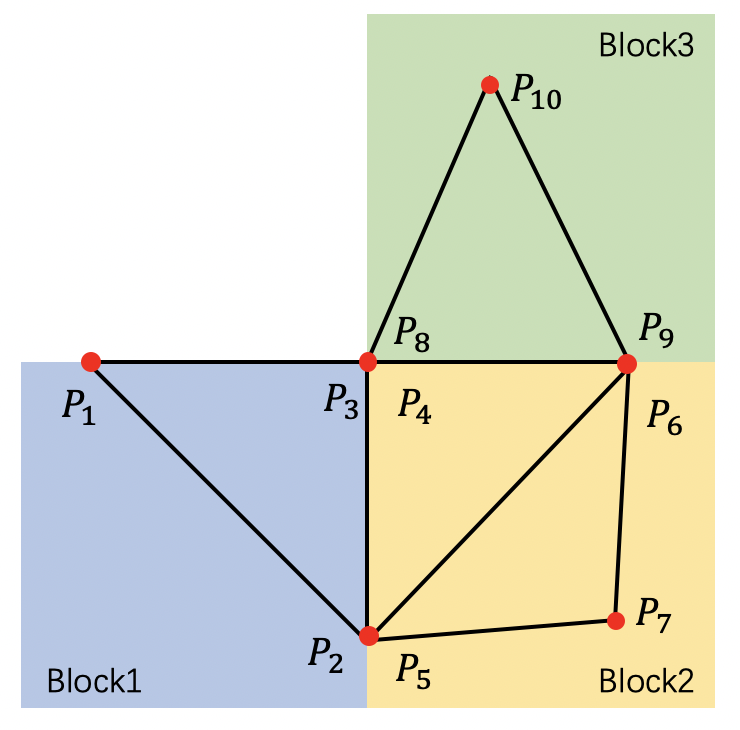
Fig 2. a two dimensional mesh map composed of three mesh blocks.

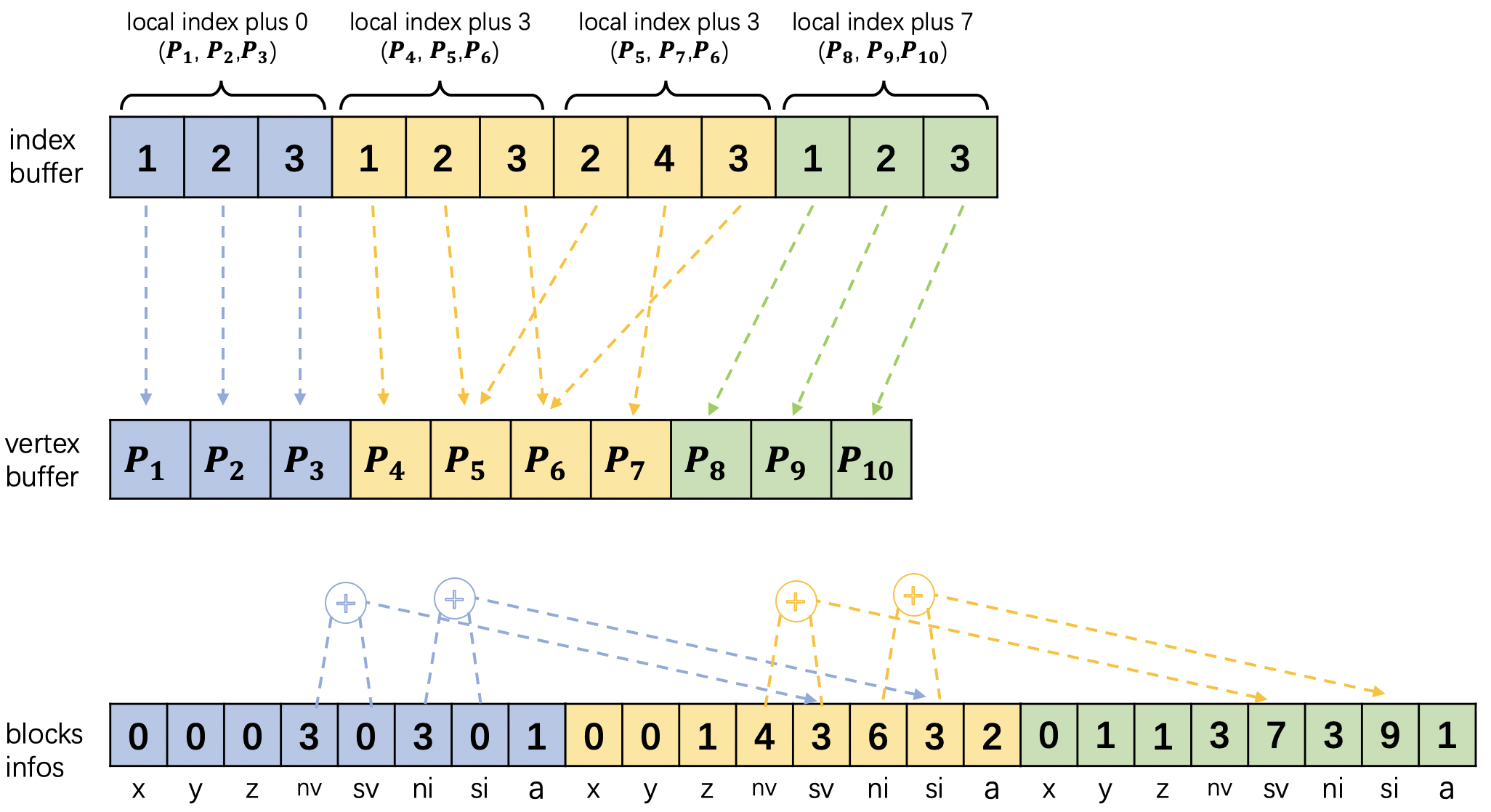
Fig 3. The relationship between the data in Block Info, Vertex Buffer and Index Buffer of the mesh map shown in Figure 2.
As shown in Figure 2, we divide the space into even cubes called Mesh Block. A Mesh Block is similar to a small mesh map, which consists of vertices and faces. We use different color to represent different Mesh Block in figure 2. No Mesh Block will be created if the space is empty for the seek of memory efficiency. Mesh Blocks may contain duplicate vertices in order to make Mesh Blocks independent from each other so that you can render them separately. The the proportion of these duplicate vertices is very small and the overhead is neglectable.
The information contained in a Mesh Block is described by BlockInfo . There are 8 elements in BlockInfo : (x,y,z,numOfVertex,startPointOfVertex,numOfIndex,startPointOfIndex,version). The meaning of these elements are explained below.
The location of a Mesh Block in the space is represented by three number: (x, y, z), each of which is an integer. Multiply (x, y, z) with the side length of Mesh Block equals to it’s physical location. When the mesh map is very large, we can filter mesh blocks by their location.
numOfVertex and numOfIndex are the number of vertices and indices in a Mesh Block. We represent faces by indices for every three indices form a triangular face. The number of faces equals to numOfIndex/3.
version tells whether the Mesh Block has been updated or not. If current version is larger than the version of cached Mesh Block, we need to update the cache.
startPointOfVertex and startPointOfIndex are two redundant auxiliary parameters. When we call getVerticesIncremental or getNormalsIncremental or getIndicesIncremental function, the result is stored in a piece of continuous memory, in which the vertices (or normals or indices) information is continuously stored. You need to extract the data of each Mesh Block by yourself. Since the number of vertices (or normals or indices) is given, you can calculate the vertex (or normal or indice) position in the buffer cumulatively. Howerer, we have calculated the starting position of vertices (or normals or indices) in the buffer, you can extract the data of Mesh Block from the buffer according to the starting position and size.
Please note that startPointOfVertex and startPointOfIndex are calculated from the origin of buffer, while the indices in the Index Buffer is not calculated form the origin of buffer, but from the internal origin of Mesh Block. In general, the index value in index buffer is a local index, so each block mesh can be rendered separately. If you want to merge the contents of multiple Mesh Blocks, you need to modify the indices from the index buffer.
Incremental Update
In some cases, we need to create and use the map at the same time while in other cases, we will build the map first and then use the completed map. In order to meet these two application scenarios, we provide two sets of functions to obtain maps. One set of functions use all as the suffix, such as getVerticesAll, getIndicesAll, etc. The other set of functions use incremental as suffix, such as getVerticesIncremental, getIndicesIncremental, etc. The former functions get all map data at once while the latter only gets the latest updated data. Please note that the data obtained by the former is just a one large map, which has not been divided into small Mesh Blocks. The data obtained by the latter is divided, however, as metioned above. Therefore, there is an extra getBlocksInfoIncremental function in the latter set of functions to get all the mesh blocks information.
Every time the function updateSceneMesh is called, the map data in SceneMesh will be updated. When the parameter passed to updateSceneMesh is True, the recently created map and all the map created before will be updated. But if the parameter is False, only the recently map created will be updated. The recently here refers to the period from the last call of updateSceneMesh to the current call.
Best Practices
To get better reconstruction results, developers can prompt users to operate as follows: 1. Move the mobile phone as much as possible and avoid rotating the mobile phone in place; 2. Do not reconstruct in places with large white or black areas, and avoid objects with reflections (such as mirrors and smooth metal), which may produce some floating debris; 3. Since the reconstruction process depends on the motion tracking system, fast moving or blocking the camera may affect the result of motion tracking, thus affecting the result of DenseSpatialMap . Therefore, the user should try to avoid fast moving or blocking the camera.
Requirements
To use Dense Spatial Map, you will need an EasyAR Motion Tracking (or ARCore / ARKit) supported device.
Better result will be obtained if the CPU’s computing power equals or exceeds Apple’s A10 / Qualcomm’s Snapdragon 835 / Huawei’s Kiri970 processor.